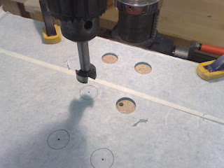
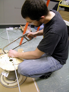
Construction of the first video interactive was started today. An existing pedestal was first lightly sanded, then, using a printed mock-up, the hole position was determined for button/switch placement.
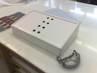
Exhibit:F design team's online diary of the exhibit installation process in a museum setting. Photo, video and written documentation of an exhibit's conception, design, planning, construction and installation.
Exhibit:F are Eric Espig and Grant Vogl. Museum Studies graduates presently working from Ottawa, Ontario, Canada. Our first major exhibit Cold War Berlin: Life at the Breaking Point opened May 12, 2009 at the Diefenbunker Museum.
Construction of the first video interactive was started today. An existing pedestal was first lightly sanded, then, using a printed mock-up, the hole position was determined for button/switch placement.
Posted by Grant Vogl at 17:08 0 comments
Labels: cases, digital, display, interactive, video
View of threaded rod and lighting box from above the ceiling tiles.
Head in the ceiling! Be extremely careful when working in old structures. I wore a respirator, goggles and long sleeves to ensure that I didn't inhale or come into contact with any dust, insulation or asbestos.
Ceiling inserts using custom hardward and existing channels in the ceiling.
Lights up! Currently, the installation is complete but the lights are not aimed or balanced.
Posted by Grant Vogl at 21:20 0 comments
Labels: asbestos, ceiling channels, halogen, installation, lighting, track lighting
Posted by Eric Espig at 20:25 0 comments
Labels: barb wire, graphics, illustrator, sign vinyl, transfer tape
Each and every one of our exhibition artifacts requires a custom mount, both to provide proper support and protection, and to work with our existing cases in a functional and aesthetic way.
We chose to work in acrylic and keep the mounts simple. Acrylic sheet was cut to size based on individual artifact needs, and bends were created using a heating element and wooden jig cut to 45 degrees. Additional supports are provided by mylar banding, the addition of support posts and shelves, and padded, and carved extruded polystyrene and muslin mounts.
We began assembling our digital video interactives this week. 2 video kiosks will be a part of the exhibit with 16 videos, 8 per interactive, available at each station. The videos will be displayed on 22" LCD screens wall mounted above the information/selection stations.
To store, play and control the video there are 4 simple and essential components:
The DV66 playback device is a simple and economical solution to meet museum video needs. 2 of the biggest advantages are that it does not use any moving parts as it is designed to playback 24/7, the other being that playback resumes automatically upon power-up. It is capable of playing up t0 99 files in sequence. The DV66 can be plugged into a/v, s-video and vga plugs.On the inside several limited options are selectable through 6 Dip switches: NTSC/Pal, Aspect ratio, Looping the first file/playing in sequence and a few others.
Video is stored on a seperatly bought Compact Flash card up to 4 Gigabytes. After some trial and error we found that using DVD MPEG-2 with AC3 audio in letterbox format gave the most reliable and best results.
The DV66 can run on its own simply scrolling through the files on the CF card, or an external controller can be connected to it. We used the DV66K, however it has been discontinued and the more versatile TV-66K is available for the same function and more.
The DV66K has 8 push buttons onboard or external switches can be wired into the screw ports for remote control of the video files, which is what we need for our interactive illuminating switches.
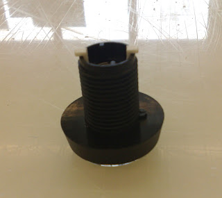
The switches have LED lights inside which will have to be wired up to a separate power supply.
The exposed posts on the bottom-side of the switches are the available connections to the LEDs
Once the switches are connected the white (common ground) wire must be separated and wired into terminal "0" the coloured wire is then screwed into the appropriatly numbered terminal: switch # 1,2,3,4....If there is insufficient space in terminal "0" (like we have run into here, an adaptation will have to be made to accommodate the 8 wires.
Posted by Eric Espig at 16:01 0 comments
Labels: controller, digital, interactive, LCD, switches, video
Hire Exhibit:F !
Click Here to contact us for more information on how we can professionally and affordably; curate, design, or build your next exhibit .